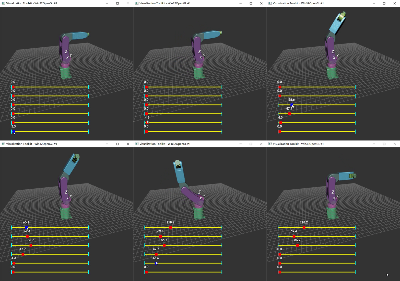
装配体Assembly
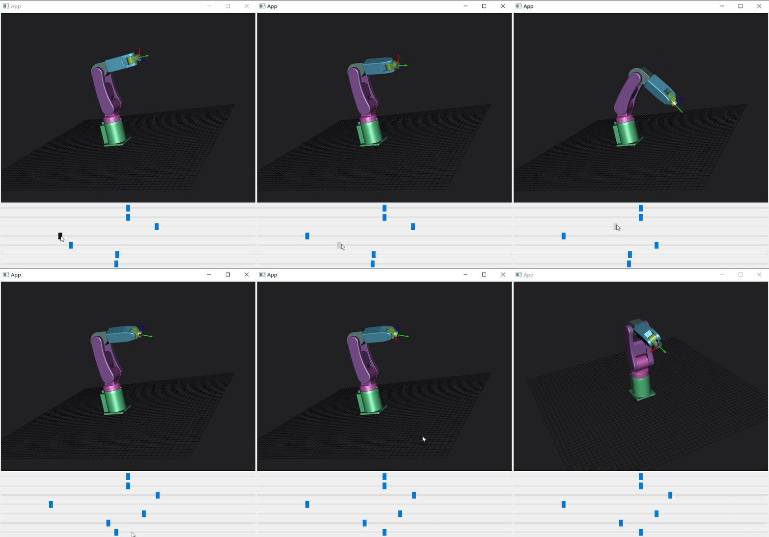
昨天晚上实现了一个可拖动的坐标轴MovableAxesWidget,今天给他加个使用场景。准备做一个简单的机械臂运动学仿真程序。
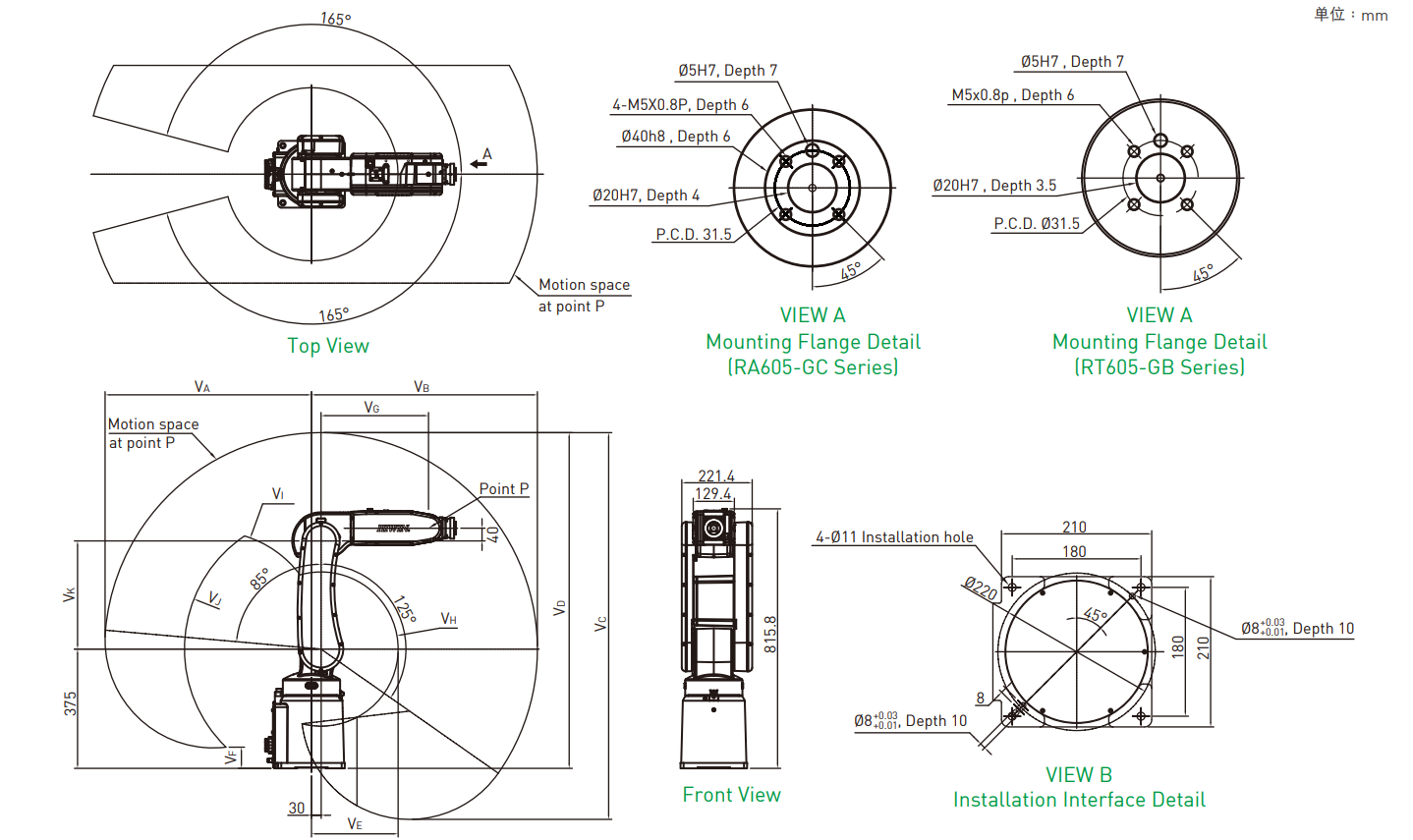
模型用的HIWIN的机械臂,官网可以下载到模型。hiwin
毕业第一份工作就是用的HIWIN的机械臂,做个demo首先想到的就是这个。
1 vtkAssembly使用(Python)

以前没用过vtkAssembly,先用Python实现下心里有谱。参考VTK中的装配体(vtkAssembly)这篇博客中的代码。
#!/usr/bin/env python
import vtk
import math
from vtk.util.colors import *
filenames = ["RA605_0.stl", "RA605_1.stl", "RA605_2.stl",
             "RA605_3.stl", "RA605_4.stl", "RA605_5.stl", "RA605_6.stl"]
dt = 1.0
angle = [0, 0]
renWin = vtk.vtkRenderWindow()
assemblys = list()
slider_shoulder = vtk.vtkSliderRepresentation2D()
slider_elbow = vtk.vtkSliderRepresentation2D()
actor = list()


class MyInteractor(vtk.vtkInteractorStyleTrackballCamera):
    def __init__(self, parent=None):
        self.AddObserver("CharEvent", self.OnCharEvent)
        self.AddObserver("KeyPressEvent", self.OnKeyPressEvent)

    def OnCharEvent(self, obj, event):
        pass

    def OnKeyPressEvent(self, obj, event):
        return


def LoadSTL(filename):
    reader = vtk.vtkSTLReader()
    reader.SetFileName(filename)
    mapper = vtk.vtkPolyDataMapper()
    mapper.SetInputConnection(reader.GetOutputPort())
    actor = vtk.vtkLODActor()
    actor.SetMapper(mapper)
    return actor


def CreateCoordinates():
    axes = vtk.vtkAxesActor()
    axes.SetTotalLength(100, 100, 100)
    axes.SetShaftType(0)
    axes.SetCylinderRadius(0.02)
    axes.GetXAxisCaptionActor2D().SetWidth(0.03)
    axes.GetYAxisCaptionActor2D().SetWidth(0.03)
    axes.GetZAxisCaptionActor2D().SetWidth(0.03)
    return axes


def SliderCallback1(obj, event):
    sliderRepres = obj.GetRepresentation()
    pos = sliderRepres.GetValue()
    assemblys[1].SetOrientation(0, 0, pos)
    renWin.Render()


def SliderCallback2(obj, event):
    sliderRepres = obj.GetRepresentation()
    pos = sliderRepres.GetValue()
    assemblys[2].SetOrientation(pos, 0, 0)
    renWin.Render()


def SliderCallback3(obj, event):
    sliderRepres = obj.GetRepresentation()
    pos = sliderRepres.GetValue()
    assemblys[3].SetOrientation(pos, 0, 0)
    renWin.Render()


def SliderCallback4(obj, event):
    sliderRepres = obj.GetRepresentation()
    pos = sliderRepres.GetValue()
    assemblys[4].SetOrientation(0, pos, 0)
    renWin.Render()


def SliderCallback5(obj, event):
    sliderRepres = obj.GetRepresentation()
    pos = sliderRepres.GetValue()
    assemblys[5].SetOrientation(pos, 0, 0)
    renWin.Render()


def SliderCallback6(obj, event):
    sliderRepres = obj.GetRepresentation()
    pos = sliderRepres.GetValue()
    assemblys[6].SetOrientation(0, pos, 0)
    renWin.Render()


def GenterSliderRep(iren, position):
    slider_widget = ConfigSlider(
        vtk.vtkSliderRepresentation2D(), position)
    slider_widget.SetInteractor(iren)
    slider_widget.EnabledOn()
    return slider_widget


def ConfigSlider(sliderRep, Yaxes):
    sliderRep.SetMinimumValue(0.0)
    sliderRep.SetMaximumValue(360.0)
    sliderRep.SetValue(0.0)  # Specify the current value for the widget
    # Change the color of the knob that slides
    sliderRep.GetSliderProperty().SetColor(1, 0, 0)
    # Change the color of the knob when the mouse is held on it
    sliderRep.GetSelectedProperty().SetColor(0, 0, 1)
    sliderRep.GetTubeProperty().SetColor(1, 1, 0)  # Change the color of the bar
    # Change the color of the ends of the bar
    sliderRep.GetCapProperty().SetColor(0, 1, 1)
    # sliderRep.GetTitleProperty().SetColor(1,0,0) # Change the color of the text displaying the value
    # Position the first end point of the slider
    sliderRep.GetPoint1Coordinate().SetCoordinateSystemToDisplay()
    sliderRep.GetPoint1Coordinate().SetValue(50, Yaxes)
    # Position the second end point of the slider
    sliderRep.GetPoint2Coordinate().SetCoordinateSystemToDisplay()
    sliderRep.GetPoint2Coordinate().SetValue(400, Yaxes)
    # Specify the length of the slider shape.The slider length by default is 0.05
    sliderRep.SetSliderLength(0.02)
    # Set the width of the slider in the directions orthogonal to the slider axis
    sliderRep.SetSliderWidth(0.02)
    sliderRep.SetTubeWidth(0.005)
    sliderRep.SetEndCapWidth(0.03)

    sliderRep.ShowSliderLabelOn()  # display the slider text label
    sliderRep.SetLabelFormat("%.1f")

    sliderWidget = vtk.vtkSliderWidget()
    sliderWidget.SetRepresentation(sliderRep)
    sliderWidget.SetAnimationModeToAnimate()

    return sliderWidget


def CreateGround():
    # create plane source
    plane = vtk.vtkPlaneSource()
    plane.SetXResolution(50)
    plane.SetYResolution(50)
    plane.SetCenter(0, 0, 0)
    plane.SetNormal(0, 0, 1)
    # mapper
    mapper = vtk.vtkPolyDataMapper()
    mapper.SetInputConnection(plane.GetOutputPort())

    # actor
    actor = vtk.vtkActor()
    actor.SetMapper(mapper)
    actor.GetProperty().SetRepresentationToWireframe()

    actor.GetProperty().SetColor(light_grey)
    transform = vtk.vtkTransform()
    transform.Scale(2000, 2000, 1)
    actor.SetUserTransform(transform)
    return actor


def CreateScene():
    # Create a rendering window and renderer
    ren = vtk.vtkRenderer()
    #renWin = vtk.vtkRenderWindow()
    renWin.AddRenderer(ren)
    # Create a renderwindowinteractor
    iren = vtk.vtkRenderWindowInteractor()
    iren.SetRenderWindow(renWin)
    style = MyInteractor()
    style.SetDefaultRenderer(ren)
    iren.SetInteractorStyle(style)

    for id, file in enumerate(filenames):
        actor.append(LoadSTL(file))
        # actor[id].GetProperty().SetColor(blue)
        r = vtk.vtkMath.Random(.4, 1.0)
        g = vtk.vtkMath.Random(.4, 1.0)
        b = vtk.vtkMath.Random(.4, 1.0)
        print(r, g, b)

        actor[id].GetProperty().SetDiffuseColor(r, g, b)
        actor[id].GetProperty().SetDiffuse(.8)
        actor[id].GetProperty().SetSpecular(.5)
        actor[id].GetProperty().SetSpecularColor(1.0, 1.0, 1.0)
        actor[id].GetProperty().SetSpecularPower(30.0)

        tmp_assembly = vtk.vtkAssembly()
        assemblys.append(tmp_assembly)
        assemblys[id].AddPart(actor[id])
        assemblys[id].SetPosition(0, 0, 0)
        if(id > 0):
            assemblys[id-1].AddPart(tmp_assembly)

    assemblys[0].SetOrigin(0,0,375)
    assemblys[1].SetOrigin(0,0,0)
    assemblys[2].SetOrigin(0,30,0)
    assemblys[3].SetOrigin(0,30,340)
    assemblys[4].SetOrigin(0,0,380)
    assemblys[5].SetOrigin(0,368,380)
    assemblys[6].SetOrigin(0,368,380)

    ren.AddActor(assemblys[0])

    # Add coordinates
    axes = CreateCoordinates()
    ren.AddActor(axes)

    # Add ground
    ground = CreateGround()
    ren.AddActor(ground)

    slider_1 = GenterSliderRep(iren,40)
    slider_2 = GenterSliderRep(iren,80)
    slider_3 = GenterSliderRep(iren,120)
    slider_4 = GenterSliderRep(iren,160)
    slider_5 = GenterSliderRep(iren,200)
    slider_6 = GenterSliderRep(iren,240)

    slider_1.AddObserver("InteractionEvent", SliderCallback1)
    slider_2.AddObserver("InteractionEvent", SliderCallback2)
    slider_3.AddObserver("InteractionEvent", SliderCallback3)
    slider_4.AddObserver("InteractionEvent", SliderCallback4)
    slider_5.AddObserver("InteractionEvent", SliderCallback5)
    slider_6.AddObserver("InteractionEvent", SliderCallback6)

    # Set background color
    ren.SetBackground(.2, .2, .2)

    # Set window size
    renWin.SetSize(600, 600)

    # Set up the camera to get a particular view of the scene
    camera = vtk.vtkCamera()
    camera.SetFocalPoint(300, 0, 0)
    camera.SetPosition(300, -400, 350)
    camera.ComputeViewPlaneNormal()
    camera.SetViewUp(0, 1, 0)
    camera.Zoom(0.4)
    ren.SetActiveCamera(camera)
    # Enable user interface interactor
    iren.Initialize()
    iren.Start()


if __name__ == "__main__":
    CreateScene()
2 运动学建模
不考虑动力学,运动学比较简单。做一个DEMO我只需要DH参数、正解方程、逆解方程即可。
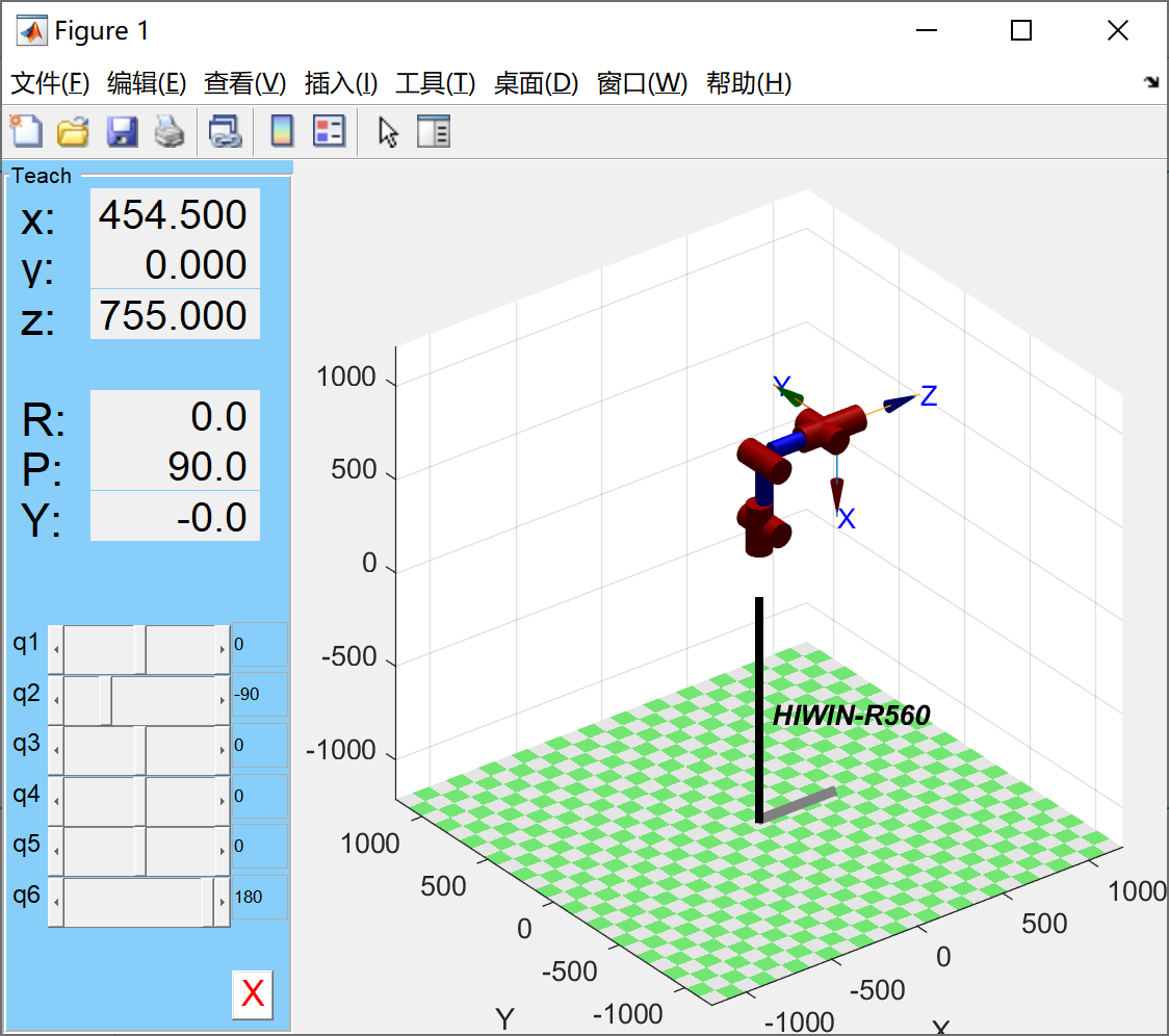
HIWIN官网也可以下载到图纸,算一下dh参数。跟matlab算的结果比较下就可以验证DH、正解找的是否正确。


clear;
clc;
close all;
%% 建模
th(1) = 0;  dh_d(1) = 375;    dh_a(1) = 0;      alp(1) = 0;
th(2) = 0;  dh_d(2) = 0;      dh_a(2) = 30;     alp(2) = -pi/2;
th(3) = 0;  dh_d(3) = 0;      dh_a(3) = 340;    alp(3) = 0;
th(4) = 0;  dh_d(4) = 338;    dh_a(4) = 40;     alp(4) = -pi/2;
th(5) = 0;  dh_d(5) = 0;      dh_a(5) = 0;      alp(5) = pi/2;
th(6) = 0;  dh_d(6) = 86.5;   dh_a(6) = 0;      alp(6) = -pi/2;
L1 = Link([th(1), dh_d(1), dh_a(1), alp(1), 0], 'modified');
L2 = Link([th(2), dh_d(2), dh_a(2), alp(2), 0], 'modified');
L3 = Link([th(3), dh_d(3), dh_a(3), alp(3), 0], 'modified');
L4 = Link([th(4), dh_d(4), dh_a(4), alp(4), 0], 'modified');
L5 = Link([th(5), dh_d(5), dh_a(5), alp(5), 0], 'modified');
L6 = Link([th(6), dh_d(6), dh_a(6), alp(6), 0], 'modified');
robot = SerialLink([L1,L2,L3,L4,L5,L6]);
robot.name='HIWIN-R560';
robot.display();

%% 正解
theta = [0, -90, 0,0,0,180]*pi/180;
robot.teach();
robot.plot(theta);
t0 = robot.fkine(theta)    %末端执行器位姿
3 vtkAssembly使用(C++)

python的代码翻译一遍,根据机械说明书找到每个轴初始角度、允许旋转角度、旋转轴、旋转中心并写成配置文件。
[Parameter]
Joints=7

[Joint0]
file = "RA605_0.stl"
type = Pedestal
color = "#66e299"
Position = "0,0,375"

[Joint1]
file = "RA605_1.stl"
type = RotatingPair
dh = "0,0,0,375"
Range = "-165,165"
color = "#e270d1"
Origin = "0,0,0"
RotateAaxis = "0, 0, 1"

[Joint2]
file = "RA605_2.stl"
type = RotatingPair
dh = "-90,30,-90,0"
Range = "-125,85"
color = "#9e68b5"
Origin = "0,30,0"
RotateAaxis = "1, 0, 0"

[Joint3]
file = "RA605_3.stl"
type = RotatingPair
dh = "0,340,0,0"
Range = "-55,185"
color = "#7a9e9b"
Origin = "0,30,340"
RotateAaxis = "1, 0, 0"

[Joint4]
file = "RA605_4.stl"
type = RotatingPair
dh = "-90,40,0,338"
Range = "-190,190"
color = "#6bcef2"
Origin = "0,0,380"
RotateAaxis = "0, 1, 0"

[Joint5]
file = "RA605_5.stl"
type = RotatingPair
dh = "-90,0,0,0"
Range = "-115,115"
color = "#aaf46d"
Origin = "0,368,380"
RotateAaxis = "1, 0, 0"

[Joint6]
file = "RA605_6.stl"
type = RotatingPair
dh = "-90,0,180,86.5"
Range = "-360,360"
color = "#8ecc9e"
Origin = "0,368,380"
RotateAaxis = "0, 1, 0"
void RobotData::Joint::Rote(const double &angle)
{
    if (type != RotatingPair) {
        return;
    }
    static const double M_Zero = 1e-6;
    if ((angle - rote_range1) < M_Zero) {
        cur_rote_angle = rote_range1;
    } else if ((angle - rote_range2) > M_Zero) {
        cur_rote_angle = rote_range2;
    } else {
        cur_rote_angle = angle;
    }
    assembly->SetOrientation(0, 0, 0);
    assembly->RotateWXYZ(cur_rote_angle,
                         rotate_axis.at(0),
                         rotate_axis.at(1),
                         rotate_axis.at(2));
}

vtkSmartPointer<vtkAssembly> RobotData::GetAssembly(const int &id)
{
    Q_ASSERT(id < joints_.size());
    return joints_[id].assembly;
}

vtkSmartPointer<vtkLODActor> RobotData::GetActor(const int &id)
{
    Q_ASSERT(id < joints_.size());
    return joints_[id].actor;
}

RobotData::RobotJointType RobotData::JointType2int(const QString &str)
{
    if (str == "Pedestal") {
        return Pedestal;
    } else if (str == "RotatingPair") {
        return RotatingPair;
    } else if (str == "SlidingPair") {
        return SlidingPair;
    } else {
        return Err;
    }
}

void RobotData::SetJointsAngle(QList<double> angle)
{
    Q_ASSERT(angle.size() == joints_.size());
    for (int i = 0; i < joints_.size(); i++) {
        joints_[i].Rote(angle.at(i));
    }
}

void RobotData::SetJointAngle(const int &id, const double &angle)
{
    Q_ASSERT(id < joints_.size());
    joints_[id].Rote(angle);
}

Eigen::MatrixXd RobotData::GetDhParam()
{
    return this->mdh_param_;
}

QList<QList<double>> RobotData::GetJointsRoteRange() const
{
    QList<QList<double>> result;
    foreach (auto joint, joints_) {
        result << QList<double> { joint.rote_range1, joint.rote_range2, joint.cur_rote_angle };
    }
    return result;
}

void RobotData::Initialize()
{
    QSettings *config = new QSettings(robot_file_, QSettings::IniFormat);
    const int joint_number = config->value("Parameter/Joints").toInt();
    const QString file_path = QFileInfo(robot_file_).path();
    mdh_param_ = Eigen::MatrixXd::Zero(joint_number, 4);
    for (int i = 0; i < joint_number; i++) {
        const QString key = QString("Joint%1").arg(i);
        const RobotJointType type = JointType2int(config->value(key + "/type").toString());
        const QColor color = QColor(config->value(key + "/color").toString());
        const QString file_name = file_path + "/" + config->value(key + "/file").toString();
        Joint joint;
        joint.type = type;
        this->LoadStl(file_name, joint);
        this->CreateActor(joint, color);
        this->CreateAssembly(joint);
        QStringList strs;
        if (type == Pedestal) {
            strs = config->value(key + "/Position").toString().split(",");
            joint.assembly->SetPosition(strs.at(0).toDouble(), strs.at(1).toDouble(), strs.at(2).toDouble());
            mdh_param_.row(i) = Eigen::MatrixXd::Zero(1, 4);
        } else if (type == RotatingPair) {
            strs = config->value(key + "/Origin").toString().split(",");
            joint.assembly->SetPosition(0, 0, 0);
            joint.assembly->SetOrigin(strs.at(0).toDouble(), strs.at(1).toDouble(), strs.at(2).toDouble());
            strs = config->value(key + "/RotateAaxis").toString().split(",");
            joint.rotate_axis = QList<double> { strs.at(0).toDouble(), strs.at(1).toDouble(), strs.at(2).toDouble() };
            strs = config->value(key + "/Range").toString().split(",");
            joint.rote_range1 = strs.at(0).toDouble();
            joint.rote_range2 = strs.at(1).toDouble();
            strs = config->value(key + "/dh").toString().split(",");
            Eigen::MatrixXd dh(1, 4);
            dh << strs.at(0).toDouble() * M_PI / 180.0,
              strs.at(1).toDouble(), strs.at(2).toDouble(),
              strs.at(3).toDouble() * M_PI / 180.0;
            mdh_param_.row(i) = dh;
            joint.cur_rote_angle = strs.at(0).toDouble();
        }
        joints_ << joint;
    }
}

void RobotData::LoadStl(const QString &file, RobotData::Joint &joint)
{

    vtkNew<vtkSTLReader> reader;
    reader->SetFileName(file.toLocal8Bit().data());
    reader->Update();

    vtkNew<vtkPolyData> vtp;
    vtp->DeepCopy(reader->GetOutput());
    joint.vtp = vtp;
}

void RobotData::CreateActor(RobotData::Joint &joint, const QColor &diffuse_color)
{
    vtkNew<vtkLODActor> actor;
    actor->GetProperty()->SetDiffuseColor(
      diffuse_color.redF(), diffuse_color.greenF(), diffuse_color.blueF());
    actor->GetProperty()->SetDiffuse(.8);
    actor->GetProperty()->SetSpecular(.5);
    actor->GetProperty()->SetSpecularColor(1, 1, 1);
    actor->GetProperty()->SetSpecularPower(30);

    vtkNew<vtkPolyDataMapper> mapper;
    mapper->SetInputData(joint.vtp);
    actor->SetMapper(mapper);

    joint.actor = actor;
}

void RobotData::CreateAssembly(RobotData::Joint &joint)
{
    vtkNew<vtkAssembly> assembly;
    joint.assembly = assembly;
    assembly->AddPart(joint.actor);

    if (joints_.size() >= 1) {
        joints_[joints_.size() - 1].assembly->AddPart(assembly);
    }
}
4 正解
正解比较简单,自己写一下,跟Matlab结果比较下就可以验证。
Manipulator::Manipulator()
{
    Eigen::MatrixXd q_init = Eigen::MatrixXd::Zero(6, 1); //关节角初始化为[0, 0, 0, 0, 0, 0]
    setJointAngle(q_init);

    Eigen::MatrixXd dh_param(6, 4); //机械臂的DH参数
    dh_param << 0, 375, 0, 0,
      -M_PI / 2, 0, 30, -M_PI / 2,
      0, 0, 340, 0,
      0, 338, 40, -M_PI / 2,
      0, 0, 0, M_PI / 2,
      M_PI, 86.5, 0, -M_PI / 2;
    setDhParam(dh_param); //初始化机械臂的DH参数

    Manipulator::joint_num = 6;
    Manipulator::arm_radius = 0.08; //机械臂连杆的半径(粗细),暂时都按最粗处80mm计算

    Manipulator::max_ang = 3 * M_PI / 4 * Eigen::MatrixXd::Ones(Manipulator::joint_num, 1); //最大关节角135°
    Manipulator::min_ang = -3 * M_PI / 4 * Eigen::MatrixXd::Ones(Manipulator::joint_num, 1); //最小关节角-135°
}
// 正运动学求解
// 输入六个关节角的大小,输入的是第2、3、5、6个关节处在笛卡尔空间的三维坐标,3×4矩阵。
Eigen::MatrixXd Manipulator::fkine(Eigen::MatrixXd joint_angle)
{ //正运动学
    Eigen::MatrixXd joint_position(3, 6);
    Eigen::MatrixXd dh = Manipulator::getDhParam();
    Eigen::Matrix4Xd T = Eigen::Matrix4Xd::Identity(4, 4);

    for (int i = 0; i < joint_angle.rows(); i++) {
        double q = dh(i, 0); //关节角
        double d = dh(i, 1); //连杆偏距
        double a = dh(i, 2); //连杆长度
        double alpha = dh(i, 3); //扭转角

        Eigen::Matrix4Xd T_temp(4, 4);

        T_temp << cos(q), -sin(q) * cos(alpha), sin(q) * sin(alpha), a * cos(q),
          sin(q), cos(q) * cos(alpha), -cos(q) * sin(alpha), a * sin(q),
          0, sin(alpha), cos(alpha), d,
          0, 0, 0, 1;

        T = T * T_temp;

        joint_position.col(i) = T.block(0, 3, 3, 1);
    }

    return joint_position;
}
5 逆解
自己写的话矩阵运算太恶心了。找了个开源的openrave,其中有一个 ikfast inverse kinematics compiler 模块。
这两个仓库有使用方式,第二个带中文注释。probot_anno_ikfast_manipulator_plugin、LizhiyuanBest/PROBOT_Anno初步试了下,结果是对的,如何集成还没想好。
本来是想给昨天写的MovableAxesWidget搞一个应用场景Demo。结果搞了半天不相关的,现在看来要做UI实现一个简单的示教器才能用到。
要找一个完整的时间来做,先告一段落。元旦再搞,做一个简单的示教器来学习。